Lithium-ion (Li-ion) batteries are an advanced technology that will play a key role in the energy transition to renewable and sustainable solutions. High energy-density, long cycle-life, and improvements in safety have driven their adoption. Applications in automotive, grid energy storage, and consumer electronics will continue to drive their growth in the coming years.
The anode is a key component of the battery of which graphite continues to be the dominant material because of low cost, abundance, non-toxicity, and structural stability. However, to improve the battery performance alternative materials are being investigated such as graphene and graphene oxide. This application note will analyze these three materials using several Micromeritics physisorption devices.
In this case study, the commonly used anode material in lithium-ion batteries, graphite, was characterized by BET surface area and DFT surface energy distribution and compared with other alternative anode materials.
Materials and Equipment
The commercial graphite anode powder (Sigma Aldrich Lot# MKCK3331), graphene (Sigma Aldrich Lot# MKCP4019), and graphene oxide (Sigma Aldrich Lot# MKCP6914) analyzed on three Micromeritics physisorption instruments: the Gemini, TriStar, and 3Flex.
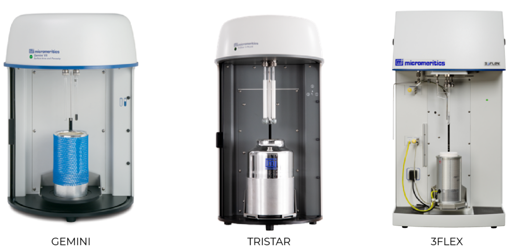
The Gemini is specifically designed for a rapid surface area measurement. It uses the adsorptive rate dosing method, where it doses at the rate the sample adsorbs gas, which allows higher speed than a typical manometric instrument. Also, having blank tube subtraction for each analysis yields accurate results with less error. This allows low surface area characterization with nitrogen adsorptive gas, which can be more affordable than analysis with krypton. The Tristar on the other hand is designed for a high-throughput lab environment, efficiently analyzing three samples in a single Dewar flask. The Tristar also has the Kr option available for low surface area BET analysis. The 3Flex is designed for high-throughput research with the most versatile functions including micropore and vapor analyses, as well as Krypton analysis, with additional options to support static or dynamic chemisorption experiments.
Experimental
All the samples were degassed under evacuation at 300°C for 60 minutes on the Smart VacPrep. After weighing the samples to obtain the after-degas sample mass, they were installed on each instrument to be analyzed with nitrogen adsorptive gas at liquid nitrogen temperature of 77K. Eleven points from 0.05 to 0.3 relative pressures were collected on the TriStar and Gemini. The full adsorption and desorption isotherms, up to saturation pressure, were collected on the 3Flex.
BET Surface Area
The BET surface area results collected from different Micromeritics’ physisorption devices shows excellent repeatability as shown in the table below.

Interestingly, when the typical 0.05-0.3 relative pressure range was selected for the BET calculations, the typical linearity requirements for reliable the BET fit were not obtained for both graphite and graphene samples. The BET calculation is shown in Figure 2 when the typical range is selected.
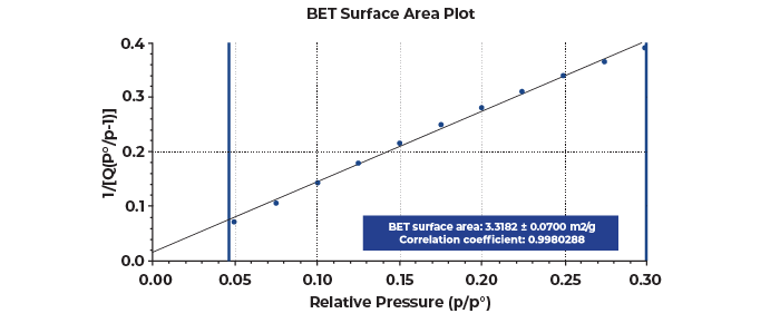
Both graphite and graphene were observed to have two linear regions in this range. These multiple linear regions are displayed more prominently on the Rouquerol transform plot shown in Figure 3, which serves as a helpful guide when selecting a proper relative pressure range for a BET calculation especially when the linear BET range deviates from the typical 0.05-0.3 relative pressures [1].
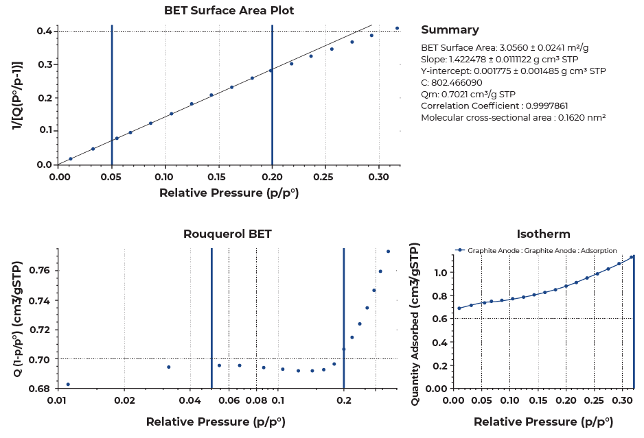
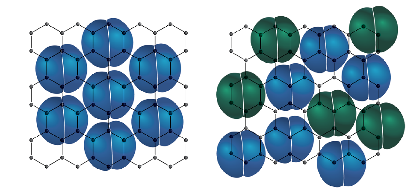
These unusual isotherms with several sub-steps reflect the effect of the commensurate transition as well as the layering transitions. The commensurate transition is a packing transition of nitrogen on the surface of a graphene sheet as the pressure increases as shown in Figure 4. At low pressures, a nitrogen molecule favorably sits on top of a graphitic ring, slightly overlapping into the adjacent rings due to its larger size. As the pressure increases, more nitrogen molecules are introduced, and they become more tightly packed together on the surface, each molecule no longer in the favorable state of directly sitting on top of the graphitic ring.
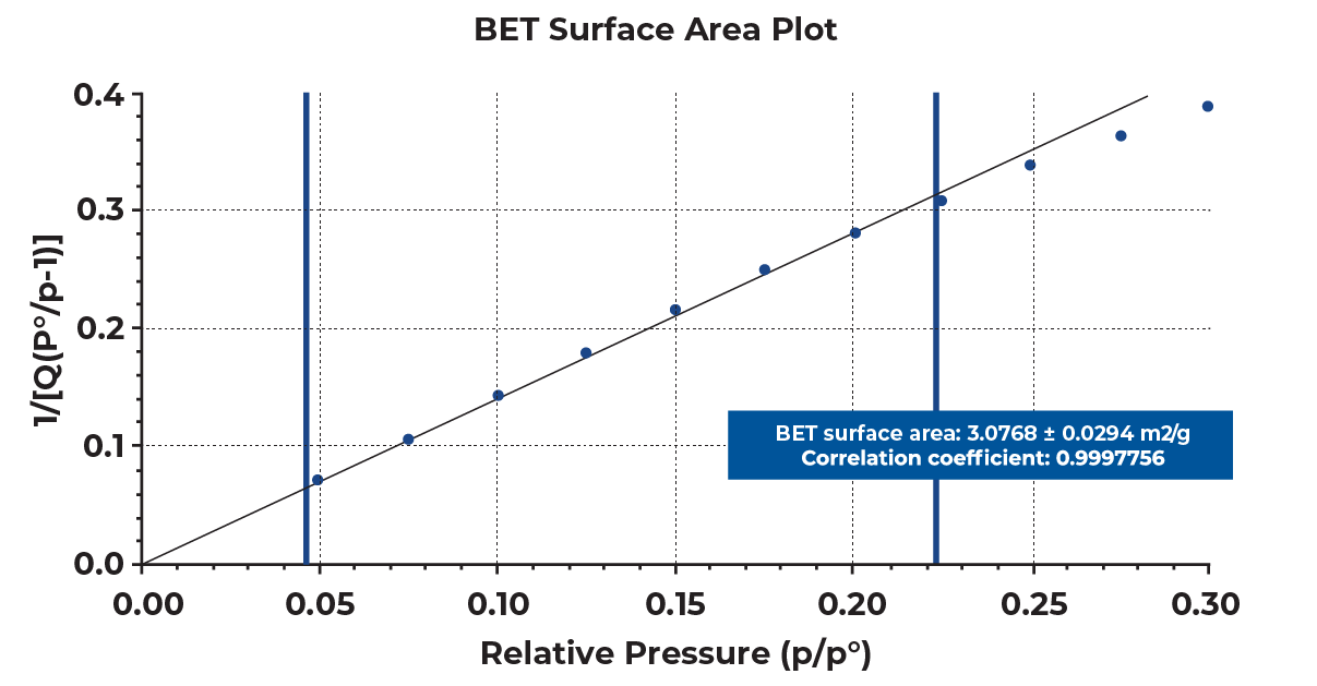
When several sub-steps are present in a collected isotherm, the lower linear region should be selected for the best estimation of BET surface area of a sample to satisfy the linearity required for BET calculations. Selecting 0.05 to 0.2 relative pressure range for the presented samples yielded good linearity with the correlation coefficient greater than 0.999 as shown in Figure 5. This pressure range can vary sample to sample, so reporting the selected pressure range along with the BET surface area for a graphitic carbon would be necessary.
DFT Surface Energy
DFT surface energy method characterizes the surface energy heterogeneity by deconvoluting an experimental isotherm based on the library of model isotherms of non-porous surfaces with different surface energies [2]. The DFT surface energy data reveals the level of interactions with an adsorptive gas present on the surface of a sample. A surface energy distribution is obtained by plotting the incremental surface area against the adsorptive potential energy (ε/k) in Kelvin, which relates to the isosteric heat of adsorption. The colder the temperature means there are less interactions between the surface and the adsorptive gas, and the warmer temperature means there are stronger interactions.
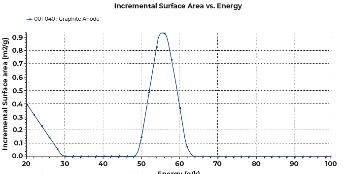
More importantly, the adsorption energy reveals the surface topology features of a graphitic surface. The adsorption potentials ranging 50-60K represents the basal planes, those below 50K represents the prismatic surfaces, and those above 60K represents the defects [3]. The adsorption potentials near 20K and near 100K represent nitrogen condensation and presence of micropores, respectively, so they are unrelated to the surface energy of the material. The surface energy distribution for the graphite anode sample is shown in Figure 6. It was mainly consisted of the basal planes with the main peak nicely centered around 50-60K.
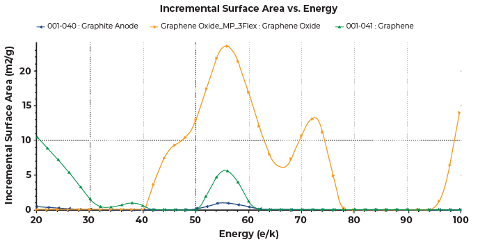
Figure 7 shows the overlay of the DFT surface energy distribution of graphite anode, graphene and graphene oxide. The graphene sample was consisted of both basal and prismatic planes. The graphene oxide was consisted of the basal, prismatic planes as well as defects where the basal plane contributed the most to the total surface area. It also showed some presence of micropore with the peak near 100K. Comparatively, the graphene had stronger interactions with nitrogen than the graphite anode sample, and graphene oxide exhibited the strongest interactions with the most surface area.
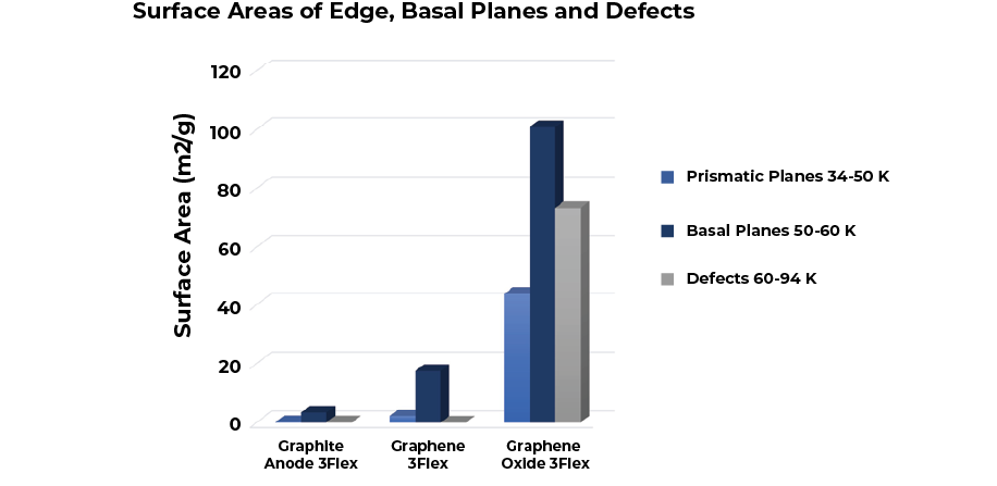
By associating different ranges of adsorptive potentials to basal, prismatic planes and defects, the same data used for the DFT surface energy distributions can be rearranged to show the surface area distribution contributing to each plane as shown in Figure 8.

Conclusion
A single run of a nitrogen adsorption isotherm can reveal in-depth information about a material. Selecting the pressure range for BET surface area for graphite and graphene deviated from the standard pressure range of 0.05 to 0.3 p/pº due to the presence of sub-steps in the isotherm that reflected the commensurate transition as well as layering transitions. The DFT surface energy reveals the surface topology features of the commonly used anode materials in lithium-ion batteries.
References
[1] J. Rouquerol, P. Llewellyn, F. Rouquerol. Stud. Surf. Sci. Catal. 160 (2007) 49-56.
[2] J.P. Olivier. Fundamentals of Adsorption (1996) 699-707.
[3] J.P. Olivier, M. Winter, J. Power Sources 97-98 (2001) 151-155.