Micromeritics’ AutoChem series of instruments is equipped with both digital and analog I/O (inputs/outputs), which may be used to control a Pfeiffer Vacuum Thermostar mass spectrometer via a single interface (Micromeritics’ part number 291/60811/00). This cable has been specifically designed to provide the hardware interface between the two instruments. The single-connector cable end is attached to the mass spectrometer*. The double-connector cable end (consisting of small and large connectors) is connected to the AutoChem. The small connector is attached to the Analog I/O and the large connector attached to the Digital I/O.
The Quadstar software package from Pfeiffer Vacuum consists of several applications which are primarily used for the configuration of the Thermostar mass spectrometer and collection of mass spectrometer data. Pfeiffer Vacuum has also developed the TG-MS software macros for use with the Quadstar software. This suite of macros used with the Quadstar software and Micromeritics’ cable interface allows AutoChem users full control of their thermostar mass spectrometer.
Several parameters must be established to utilize the Quadstar software to the fullest. A simple thermocouple calibration is the most significant.
- Launch the Quadstar Parset program; use one of the following methods:
- Select Start > Programs > Quadstar > Parset
- Double-click the Quadstar icon on the Windows desktop, then double-click the Parset icon.
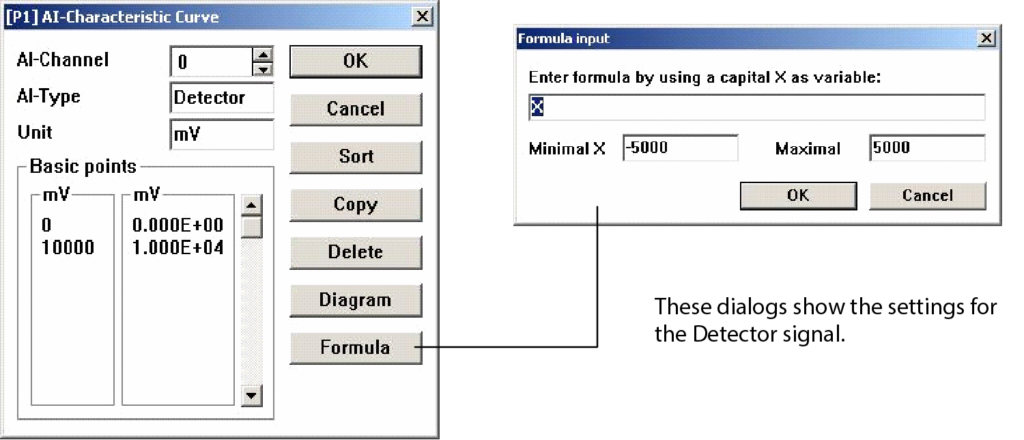
2. Select Config > AI Characteristic Curve; the AI Characteristic Curve dialog is displayed. Use this dialog to define parameters for the Detector and Thermocouple signals.
3. Configure the Detector signal as follows:
a. Click the up/down arrow in the AI-Channel field until 0 is displayed.
b. Enter Detector in the AI-Type field.
c. Enter mV in the Unit field.
d. Click Formula; enter X as the formula, -5000 in the Minimal X field and 5000 in the Maximal field.
*The cover must be removed from the Thermostar to make this connection; refer to the Thermostar manual for instructions on removing the cover.
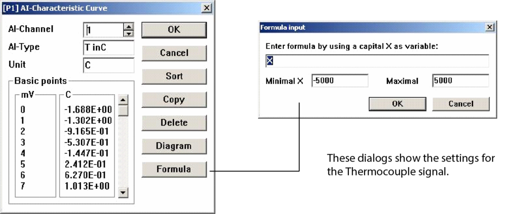
- Configure the Thermocouple signal:
a. Click the up/down arrow in the AI-Channel field until 1 is displayed. All parameters defined for 0 (Detector) are saved automatically when 1 displays.
b. Enter T inC in the AI-Type field. Be sure to space between T and inC; otherwise, the AutoChem software cannot properly identify the temperature signals.
c. Enter C in the Unit field.
d. Click Formula; enter X as the formula, -5000 in the Minimal X field and 5000 in the Maximal field.
5. Click OK to close the AI-Characteristic Curve dialog.
With these parameters set, you can now develop a thermocouple calibration.
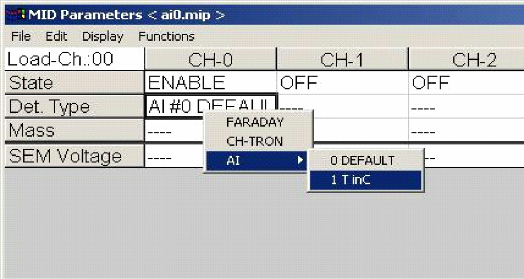
- Select Measure > MID from the main menu of the Parset application; the MID Parameters dialog is displayed. This dialog is used to specify the signals to be recorded by the Thermostar.
- Choose parameters for the calibration:
a. Right-click in the State > CH-0 field; select Enable from the pop-up menu.
b. Right-click in the Det. Type > CH-0 field; select A1 > T inC.
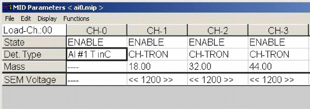
- Specify mass signals (required for the Thermostar to collect data); an example is given here. Save this file as mstcal.mip. Refer to your Thermostar instruction manual if assistance is needed for this
step.
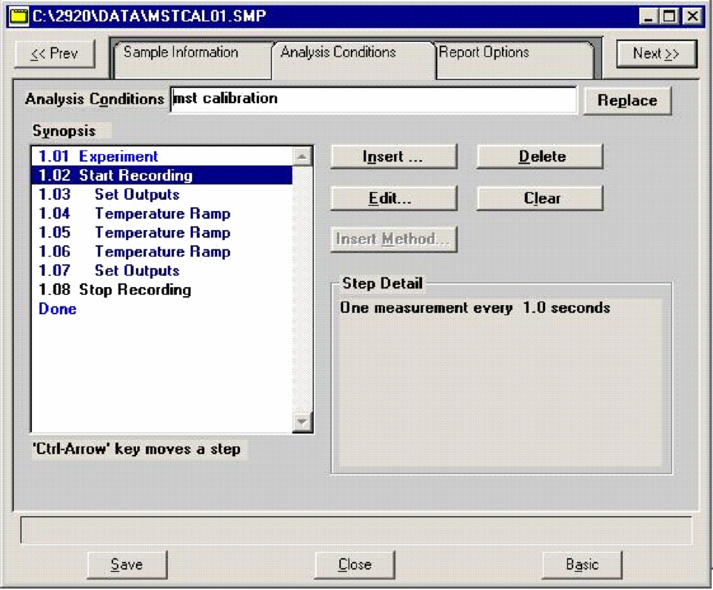
- Create a sample file (AutoChem software) for the thermocouple calibration; in this example we use mstcal01.smp. On the Analysis Conditions dialog, define the parameters as follows:

The synopsis in your sample file should look similar to the following:
- Click the TG-MS V5 icon (on your desktop) to start the program.
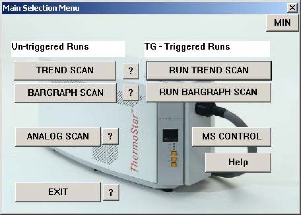
Untriggered Runs are for manual operation and TG-Triggered Runs are for operation using the AutoChem.
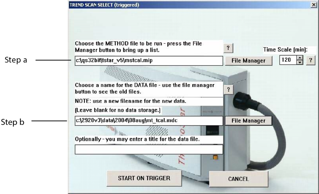
- Click RUN TREND SCAN to display the Trend Scan Select (triggered) dialog.
a. Click File Manager (upper one) and choose mstcal.mip for the method to run.
b. Click File Manager (lower one); enter a file name for the calibration data, this example uses mt_tcal.mdc.
c. Click START ON TRIGGER to close the dialog; the Thermostar is now being controlled by the AutoChem software.
- From the AutoChem software, select Unit 1 > Start Analysis; choose mstcal01.smp as the sample file.
- Click Next to start the analysis.
Data will be recorded by both the AutoChem and the Thermostar. Example data are shown in Figures 1 and 2.
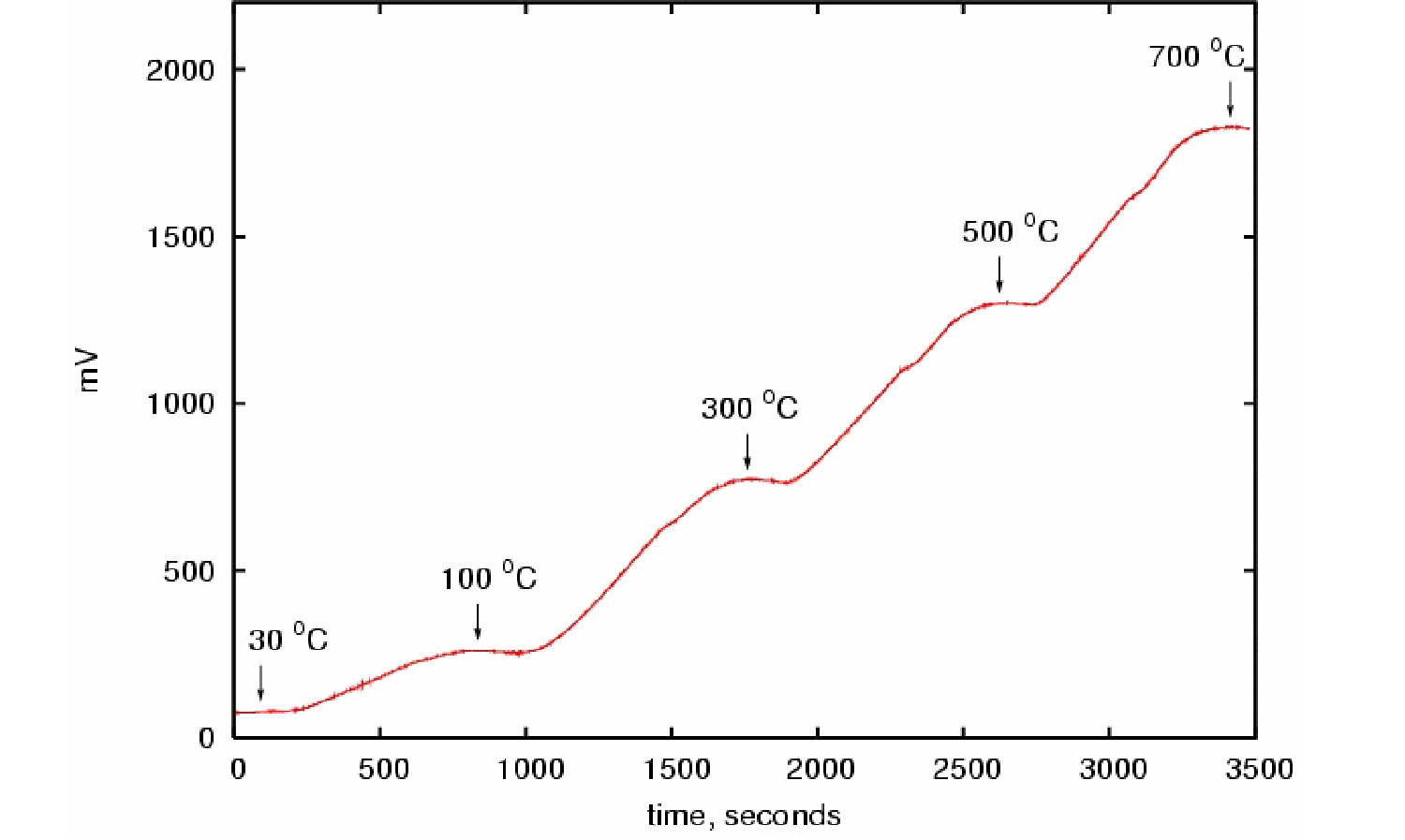
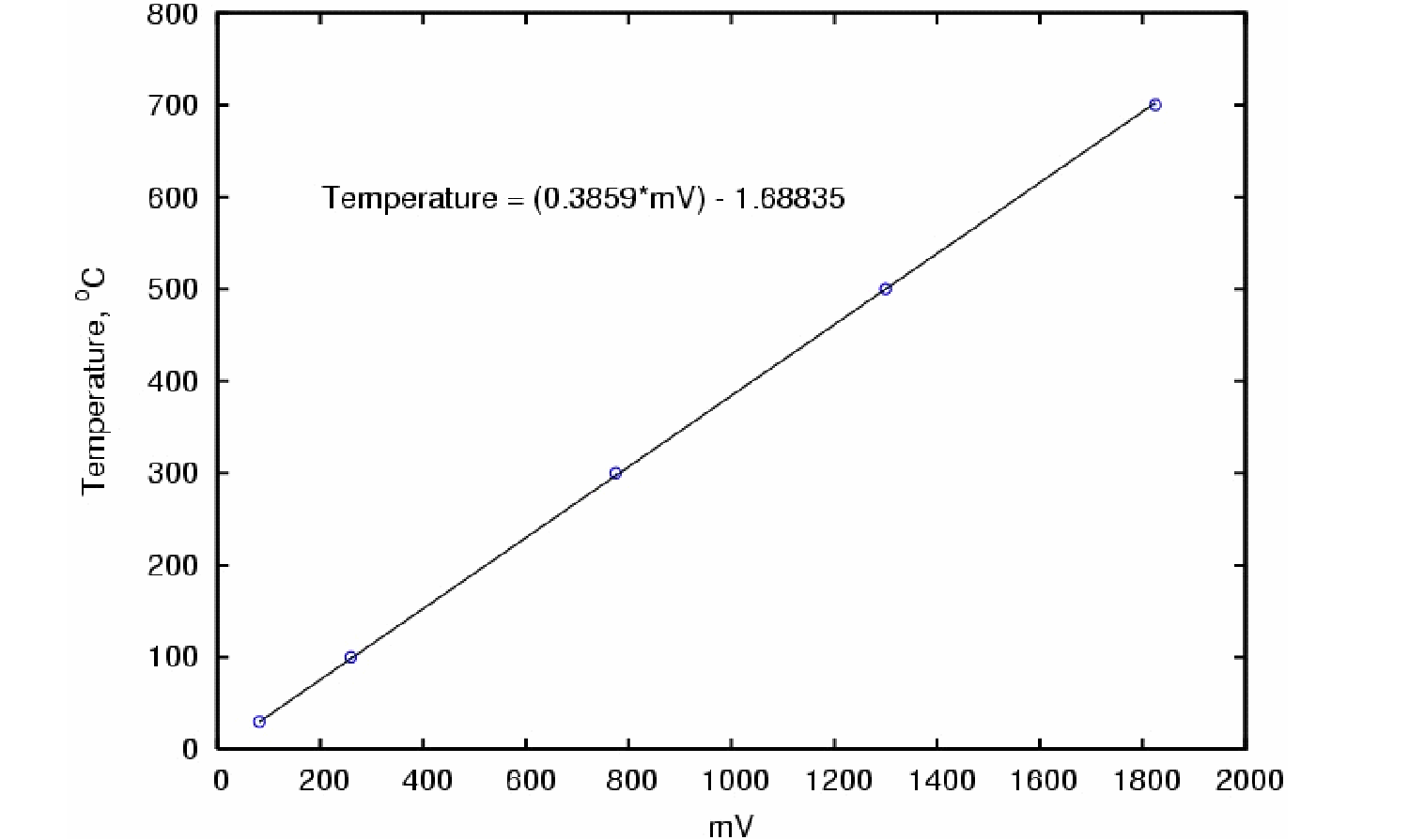
The Thermostar signal versus AutoChem temperature plot (Figure 2) yields a linear relationship. To update the AI-1 Characteristic curve:
- Select Config > AI Characteristic Curve from the main menu of the Parset application.
- Click the up/down arrow in the AI-Channel field until 1 is displayed.
- Enter the value displayed for the temperature.
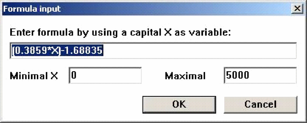
Future analyses will now contain a temperature signal in addition to any mass signals that are recorded.