Fuel cells were first conceived in 1838 by Swiss scientist Christian Schönbein; the first fuel cell was developed by Welsh scientist Sir Willian Grove in 1843. The first practical applications of fuel cells came in the 1960s for the U. S. space program. Both energy and water could be generated from two widely available fuels — hydrogen and water. Ongoing environmental concerns and energy research have fueled renewed interest in hydrogen generation and hydrogen storage as technologies required for clean, portable energy.
Quantifying the hydrogen storage capacity of new materials is a key technology for predicting the performance in a fuel cell or hydrogen storage device. The Micromeritics ASAP 2020 is a flexible gas adsorption analyzer capable of measuring the hydrogen adsorption capacity of powders and porous materials. The ASAP 2020 software has been enhanced to address the needs of fuel cell and hydrogen storage researchers. The following enhancements were introduced in Version 3 of the ASAP 2020 software:
- Absolute pressure dosing for non-condensing probe molecules like hydrogen.
- New isotherm reports that include the weight percent of hydrogen adsorbed and the Pressure Composition Isotherm that is frequently used by hydrogen storage researchers.
- Calculated Free-space options to reduce analysis time, improve precision, and minimize exposure to interfering gases like helium.
A successful hydrogen adsorption analysis requires proper sample preparation, which is a two-step process. First, samples should be degassed on the preparation port to remove moisture and stray gases like CO2 that sorb strongly to many materials at ambient temperature and pressure. Second, the sample should be degassed thoroughly on the sample port.
The standard ASAP 2020 sample tube (1/2-inch stem) with a seal frit is recommended for this type of analysis. An isothermal jacket is recommended if the analysis is conducted at cryogenic temperatures (liquid nitrogen or liquid argon). A filler rod is optional but not recommended if the analysis is performed at cryogenic temperatures; the filler rod may interfere with the precision of low-pressure measurements.
Creating the Sample File
Create a new sample file; specify conditions as follows.
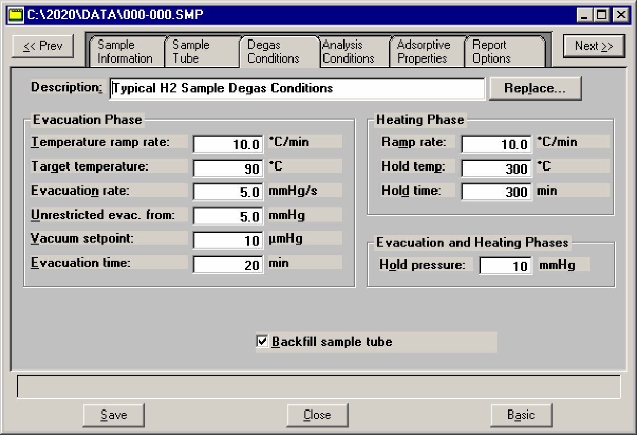
- Click the Degas Conditions tab; enter the following conditions:
a. Evacuation phase: This phase provides a simultaneous temperature ramp and evacuation. Evacuation time starts after the vacuum set point has been reached.
Temperature ramp rate: 10 °C/min
Target temperature: 90 °C (facilitates removal of moisture and minimizes steaming to prevent loss of surface area)
Evacuation rate: 5 mmHg/s (minimizes sample bed fluidization)
b. Heating phase: This phase provides a second temperature ramp after the Evacuation phase has completed.
Ramp rate: 10 °C/min
Hold temp.: 300 °C
Hold time: 300 min
c. Evacuation and Heating Phases: These phases have a maximum pressure set point. During either phase, the sample tube pressure must remain below the Hold pressure set point. If the set point pressure is exceeded, the temperature ramp is halted until the sample is evacuated to a pressure below the set point. This hold pressure set point is used to minimize the rapid liberation of moisture or stray gases that may damage the fine pore structure of the sample.
Hold pressure: 10 mmHg
d. Select Backfill sample tube.
Your Degas Conditions dialog should look this:
- Click Save, then click the Analysis Conditions tab. The Analysis Conditions may be optimized to complement the conditions specified for degassing. All evacuation settings in the analysis protocol may be minimized (set to zero). No additional evacuations are required.
a. Select the Absolute pressure dosing option.
b. Enter an appropriate pressure table; the maximum pressure should not exceed 850 mmHg.
c. Click Preparation; the Analysis Preparation dialog is displayed. Select Fast evacuation and enter 0.00 (zero) minutes for the Evacuation time. The sample will be evacuated using the conditions specified in the Degas Conditions dialog (Step 3).
d. Click Free Space; the Free Space dialog is displayed. Select Enter or Calculate. Refer to Micromeritics’ Application Note 104 (available at www.micromeritics.com) for determining the sample free space.
e. Click p0 and T; the p0 and Temperature dialog is displayed. Option #4 should be selected; enter the bath temperature in the field provided at the bottom of the dialog.
f. Click Dosing; the Dosing Options dialog is displayed. Select Low pressure incremental dose mode; enter 1 cm3/g in the Dose amount field. Leave default values in the remaining fields.
g. Click Equilibration; the Equilibration dialog is displayed. Enter 45 as the Equilibration Interval.
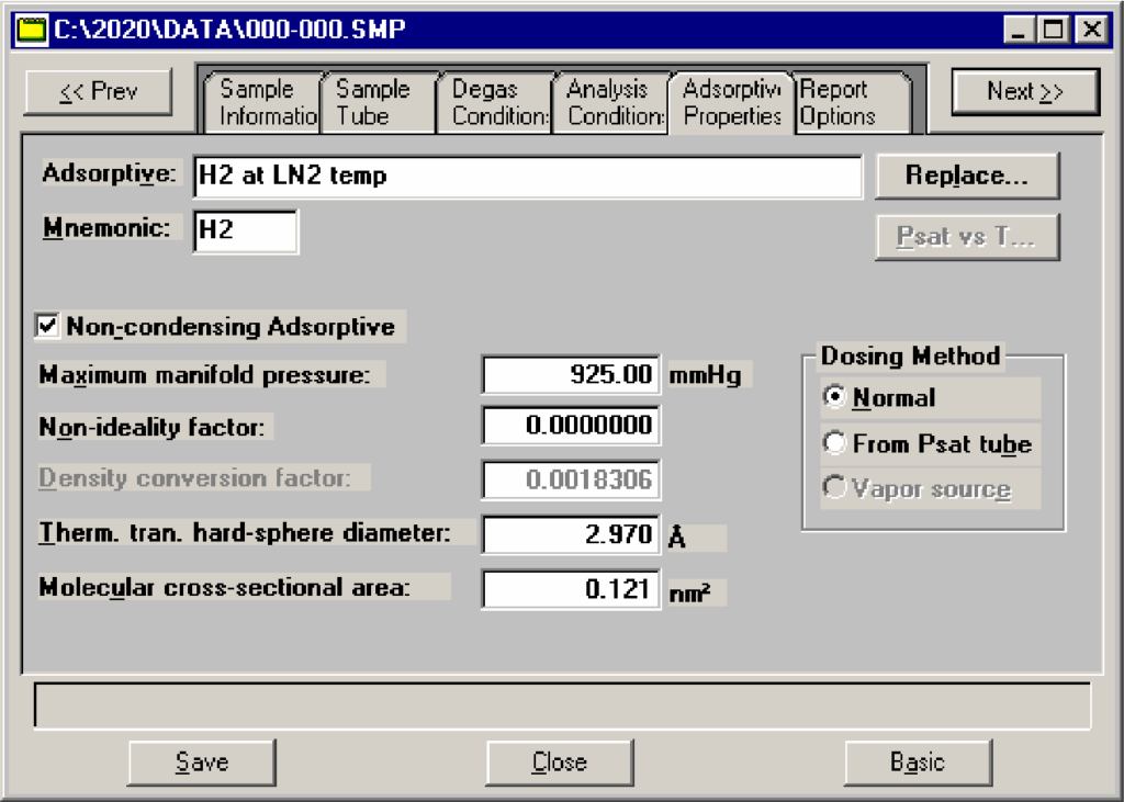
h. Click Backfill; the Sample Backfill Options dialog is displayed. Deselect Backfill sample at start of analysis. Message #4020 will display; click Yes to close the dialog. - Click Save, then click the Adsorptive Properties tab. The adsorptive properties for hydrogen are easily obtained by modifying the adsorptive properties of any adsorbate.
a. Change the mnemonic to H2. Ensure it matches the gases connected to the analyzer.
b. Select Non-condensing Adsorptive.
c. Enter 0 (zero) in the Non-ideality factor field. Leave default values in the remaining fields.
d. Enter 2.97 in the Therm. tran. Hard-sphere diameter field.
e. Enter 0.121 as the Molecular cross-sectional area.
Your Adsorptive Properties dialog should look like this:
- Click Save, then click the Report Options tab.
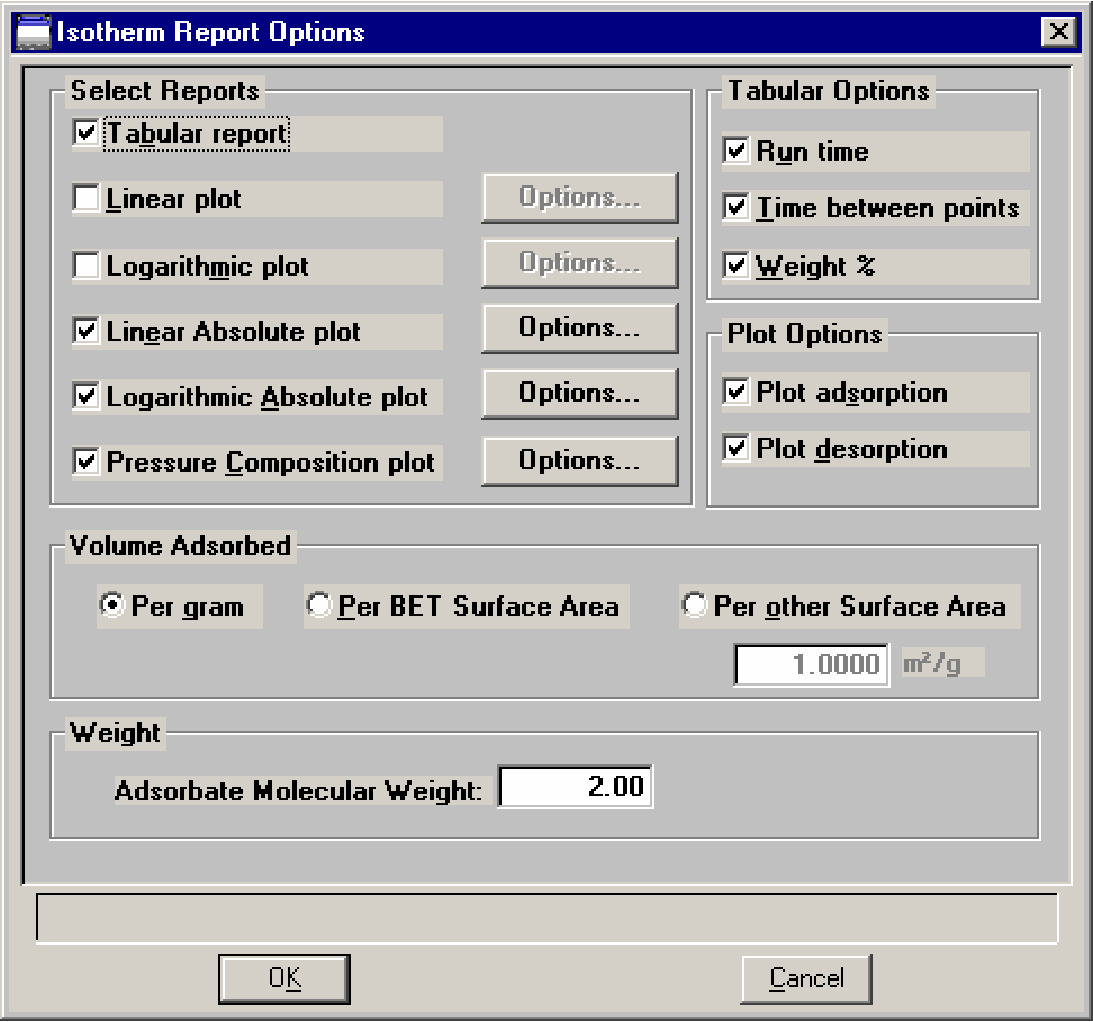
a. Double-click on the Isotherm report to select it, then click Edit; the Isotherm Report Options dialog is displayed.
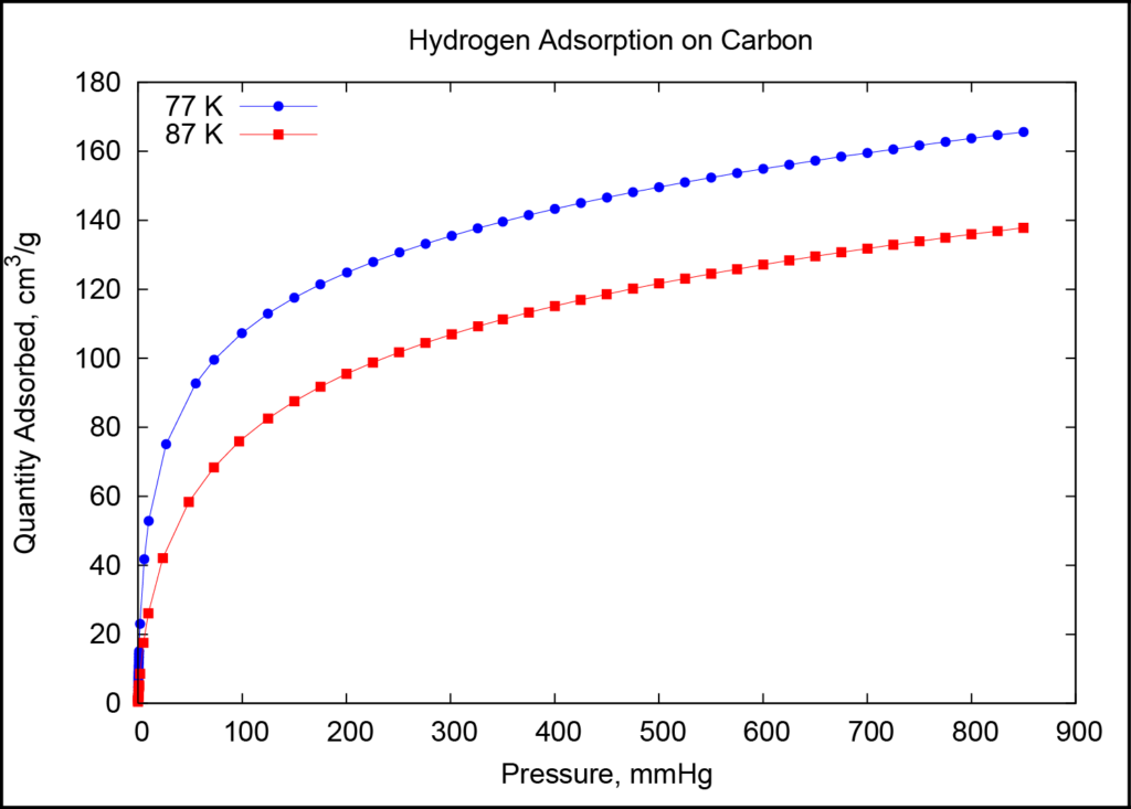
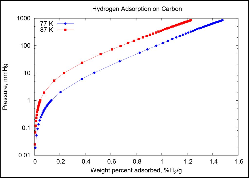
b. Select Tabular report, Linear Absolute plot (example data shown in Figure 1), Logarithmic Absolute plot, and Pressure Composition plot (example data shown in Figure 2).
c. Under Tabular Options, select Weight %.
d. Ensure that 2.00 is the value in the Adsorbate Molecular Weight field.
Leave defaults in all other fields; your Isotherm Report Options dialog should look like this:
Degassing the Sample
The sample should be degassed on a degas port first, then on the sample port.
- Install the sample tube onto a degassing port.
- Select Unit [n] > Start Degas; the Automatic Degas dialog and the Degas Status dialog are displayed.
- Click Browse and select the sample file you created.
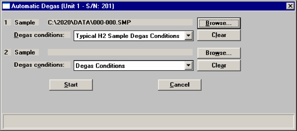
- Click Start to begin the degassing operation; you can observe the status on the status dialog.
- After this initial degas has completed, remove the sample tube from the degassing port.
- Install an Isothermal jacket on the sample tube if you are using a cryogen bath for temperature control.
- Install the sample tube onto the sample port; slide the isothermal jacket upward until it touches the sample port.
- Install the heating mantle from degassing port 2 on the sample tube. The degas heating mantle should be at least 1 cm below the isothermal jacket. Applying direct heat to the isothermal jacket may discolor and permanently damage the isothermal jacket.
- Select Unit [n] > Show Instrument Schematic, then enable manual control.
- Close all valves.
- Open valves: nitrogen valve (typically valve P1), PS, 4, 5, and 7.
- Allow the manifold to fill to 780 mmHg of nitrogen.
- Close valves: PS, 4, and 5; valve 7 should remain open.
- Open valves 9 and 2.
- Allow the manifold and sample to evacuate to less than 5 mmHg.
- Open valve 1.
- Close valves 2 and 7.
- Select Unit [n] > Degas > Show Degas Schematic, then enable Degas manual control.
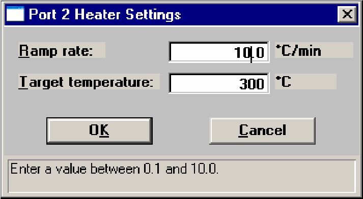
- Right-click on the sample tube icon on port 2 and select Set; the Port 2 Heater Settings dialog is displayed. Enter 10 as the Ramp rate and 300 as the Target temperature. Then click OK to close the dialog.
20. Allow the sample to degas overnight at 300 °C; a minimum of 12 hours is recommended.
Performing the Analysis
- After degassing is complete, remove the heating mantle and wait for the tube to cool to near ambient temperature. Carefully slide the isothermal jacket downward until it touches the top of the sample bulb.
- Prepare a Dewar with cryogen (or use a recirculating bath).
- Place the Dewar on the sample stand.
- Select Unit [n] > Sample Analysis, choose the sample file you created, and begin your analysis.